


 About us
  Events
  Press area
  Contact us
  General News & Events
  Product Information
  Applications
  Technical
  Product Pictures
  Latest videos
  Product Guide
 Before contacting us for support, here’s a list of frequently asked questions with helpful answers. Your can also check out and download product handbooks from here.
Our searchable news blog here has lost of information on apps, 3rd party product integration and product installation. You’ll also find videos on all our products and helpful setup on our Youtube channel here.
4G Connect
We have been asked by many boaters “What’s the best solution for boat video monitoring?” There are lots of dedicated (and expensive) marine solutions which could connect to the 4G Connect or 4G Xtream network but there’s also the simple and popular Arlo home based system which can be used. Arlo started life as part of Netgear but became a stand alone listed company back in 2018. Their products can be bought from Amazon, Best Buy etc.
The system comprises small, waterproof, battery powered cameras that connect to an Arlo hub via wifi. It means you don’t have to run wires around the boat or even find 12V power and you can position the camera in different locations as you need to. Multiple cameras are also supported.
Other IP cameras can also be connected to the 4G Connect and 4G Xtream.
4G Xtream ships with dual external antennas. They should be mounted at least 50 cm apart for optimum performance. While height is advantageous, consideration should also be given to cable runs. The standard cables (LMR200) are 7m in length and should not be extended.
Typical mounting locations would be the 1st set of spreaders on a sailboat, radar arch or stern pole/solar panel platform.
Optional 10 and 20m assemblies are available and these use LMR400 specialist coax for minimum losses.
4G Xtream
We have been asked by many boaters “What’s the best solution for boat video monitoring?” There are lots of dedicated (and expensive) marine solutions which could connect to the 4G Connect or 4G Xtream network but there’s also the simple and popular Arlo home based system which can be used. Arlo started life as part of Netgear but became a stand alone listed company back in 2018. Their products can be bought from Amazon, Best Buy etc.
The system comprises small, waterproof, battery powered cameras that connect to an Arlo hub via wifi. It means you don’t have to run wires around the boat or even find 12V power and you can position the camera in different locations as you need to. Multiple cameras are also supported.
Other IP cameras can also be connected to the 4G Connect and 4G Xtream.
Yes this is possible. One Wi-Fi network can be used to access a shoreside hotspot (2.4GHz) and the 5GHz network bridged to provide local access however this isn’t recommended or supported.
We recommend the use of our WL510 connected to the WAN port if long range Wi-Fi hotspot access is required.
4G Xtream has a built in NMEA 2000 interface which allows NMEA 2000 data to be utilised by apps on mobile devices connected to the system. GPS, AIS and instrument data are streamed from the boat’s system across the Wi-Fi network. The simplest method of viewing this data remotely would be to set up a VPN (Virtual Private Network) which effectively builds a data “tunnel” from one network (say on the shore) to another (eg: on the boat).
4G Xtream supports VPNs and this technology is well proven but requires specialist 3 rd party IP network knowledge to implement. 4G Xtream also supports MQTT for IOT applications and ZeroTier for remote access and we expect to see 3rd party marine applications develop for these platforms. 4G Xtream also supports text message polling of GPS data and alerts through its internal GPS function.
The 4G/5G Xtream has dual SIM slots (with auto fail over if required).
Inserting the SIM card is very easy. The SIM slot is in the front cap of the unit. You don’t need to open the unit.
It is very simple to configure the 4G/5G Xtream. This video below explains you how to configure the 4G/5G Xtream.
APN stands for Access Point Name and are the settings your 4GXtream needs to pass to the network carrier; AT&T, Vodafone, T-Mobile, etc. in order for the carrier to allocate your 4GXtream an IP address and connect you to the right secure network.
With the 4GConnect, you have to manually enter the APN settings of your SIM card. However, with the 4G Xtream, it has a “Auto-APN” feature that reads the SIM details and selects the correct APN settings for the SIM’s mobile network.
| Feature | 4G Xtream | 5G Xtream |
| Modem Specification | MIMO technology Cat 6 Modem. Up to 300 MB/s
Quad Core ARM Cortex A7 717 MHz Processor 256 MB RAM. |
5G Sub-6Ghz SA/NSA. Up to 2.1/3.3Gbps downlink (4×4 MIMO)
4G Cat 20 Modem. Up to 2GBs Quad Core ARM Cortex A7 717 MHz Processor 256 MB RAM. |
| 4G Antennas | Dual external wide band high gain MIMO supplied with 7m cables and mounting bases. (10 & 20m options available) | Dual external wide band high gain MIMO supplied with 7m cables and mounting bases. (10 & 20m options available) PLUS additional 100mm dome antenna for 4 x 4 MIMO operation and optimised for 5G (7m cable only) |
| Internal WiFi | Dual band independent 2.4 & 5 GHz 802.11 b/g/n/ac
Maximum 150 connections Dual antennas |
Dual band independent 2.4 & 5 GHz 802.11
b/g/n/ac Maximum 150 connections Dual antennas |
| SIM Slots | 2 | 2 |
| GPS | YES | YES |
| NMEA interfacing | Built in certified NMEA 2000 interface for NMEA 2000 data distribution over wifi | Optional with LANLink N2K external interface |
4G Xtream ships with dual external antennas. They should be mounted at least 50 cm apart for optimum performance. While height is advantageous, consideration should also be given to cable runs. The standard cables (LMR200) are 7m in length and should not be extended.
Typical mounting locations would be the 1st set of spreaders on a sailboat, radar arch or stern pole/solar panel platform.
Optional 10 and 20m assemblies are available and these use LMR400 specialist coax for minimum losses.
5G Xtream ships with dual external antennas. They should be mounted at least 50 cm apart for optimum performance. While height is advantageous, consideration should also be given to cable runs. The standard cables (LMR200) are 7m in length and should not be extended. Typical mounting locations would be the 1st set of spreaders on a sailboat, radar arch or stern pole/solar panel platform. Optional 10 and 20m assemblies are available and these use LMR400 specialist coax for minimum losses.
For the 3rd antenna dedicated to 5G frequencies, it comes with a 7m cable.
4GXtream comes in two models: ROW or USA
| Part Number | Regions | Details |
| 4G Xtream ROW version | Europe, Middle East, Africa, APAC, Malaysia, Brazil and Australasia | 4G (LTE-FDD): B1, B3, B5, B7, B8, B20, B28, B32 4G (LTE-TDD): B38, B40, B41 3G: B1, B3, B5, B8 |
| 4G Xtream US Version | North America | 4G (LTE-FDD): B2, B4, B5, B7, B12, B13, B25, B26, B29,B30, B66 3G: B2, B4, B5 |
The 4G Xtream has a CAT 6 modem so it offers fast connectivity at up to 300 MBs (network dependent).
It also supports carrier aggregation where two LTE channels can be used at the same time to double the bandwidth (network dependent).
ais receiver
No, we supply a version of our Smartertrack software free with every AIS product. The same software can also be upgraded at a later point to a full function navigation package with Navionics charts.
If the AIS transponder doesn’t have a built-in VHF splitter (i.e. AIT5000), there are 2 options: either install a dedicated VHF antenna for AIS or install an antenna splitter so that the main VHF antenna is used for both VHF radio and AIS.
For those who want to use their existing VHF antenna, then we recommend the use of a certified zero loss VHF antenna splitter such as our SPL1500 and SPL2000. Please do not use a non-zero loss certified VHF antenna splitter. They are inexpensive, but they can destroy your AIS transponder.
For those who want to install a VHF antenna dedicated to AIS, then we recommend a VHF antenna tuned to AIS frequencies. The AIS transmission and reception works on 2 dedicated channels which use the frequencies 161.975 and 162.025 MHz (channel 87B and 88B). VHF frequencies in the maritime environment use frequencies from 156.0 to 162.025 MHz and most VHF antennas are designed to provide maximum gain on channel 16 (156.8 MHz). You can now find antennas on the market dedicated to AIS frequencies such as the HA156 antenna.
These antennas, dedicated to AIS frequencies, offer maximum gain at 162 MHz (which is the centre between the 2 AIS frequencies 161.975 and 162.025 MHz). So if you install a VHF antenna instead of a VHF antenna splitter for your AIS receiver or transponder, then choose an AIS frequency VHF antenna to compensate for the loss due to the installation of the antenna lower down than the main VHF antenna at the top of the mast. The graph below shows how a dedicated AIS frequency antenna (162 MHz) provides a better VSWR and therefore a better transmission and reception.
An AIS which sends and receives data is known as a transceiver (or often called a transponder). There are also simple devices called AIS receivers which pick up transmissions and decode for displaying on a compatible chart plotter or PC based navigation system – or even an iPad or tablet.
AIS transponders will allow you to receive data from vessels close to you, but will also allow you to continuously transmit your vessel’s identity, position, speed and heading, as well as other relevant information, to all other AIS-equipped vessels within your range.
To transmit its position, an AIS transponder must have its own GPS antenna. All our AIS transponders are supplied with a GPS antenna or have a built-in GPS antenna.
ais transponder usb
This is a very valid question. After spending several hours installing a transponder, it is understandably important to confirm that it is operating correctly. The proAIS2 configuration software allows you to verify that the GPS position is valid, monitor the reception of AIS signals from other vessels, and confirm that there are no errors or alarms. However, for those new to AIS, there is often a lingering uncertainty about whether your own vessel is being seen by others.
The most reliable way to test a Class B+ AIS transponder is to ask another vessel in your marina that is equipped with AIS to confirm that they are receiving your transmissions. When your vessel is stationary, the transponder transmits approximately every three minutes. Once your speed over ground (SOG) exceeds 2 knots, the transmission rate increases to every 30 seconds. For this reason, it is important to allow sufficient time for your signal to be detected. Additionally, upon initial reception, other vessels will see only your dynamic data—position, speed, course, and MMSI number. It may take up to six minutes for your static data (vessel name, call sign, vessel type, dimensions, etc.) to be received. This behavior is normal and reflects how the AIS system manages data transmission bandwidth.
Another increasingly common method of verifying AIS operation is to check one of the online “live” AIS tracking websites. Among the free services available, MarineTraffic.com is one of the most widely used.
It is important, however, to understand the limitations of these online platforms and not to assume that your vessel will always be visible on them. The accuracy and availability of these services depend entirely on their network of AIS receiving stations, which are often operated by volunteers and enthusiasts. Coverage can be excellent in some areas, but gaps in reception do exist.
The AIS transponder can be configured with the free PC/Mac software called ProAIS2. The ProAIS2 software can be downloaded free of charge directly from our website. The functionality of the proAIS2 software is the same on Windows or Mac.
Installation of the proAIS2 software, also installs the USB drivers and we recommend not plugging the transponders USB cable in to the PC/Mac until after you have installed proAIS2. Once the installation is complete, plug the USB cable in to the computer to complete the USB driver installation. The transponder receives enough power from the USB connection to power the processor and ancillory circuitry required to configure the transponder, however the GPS will not get a fix, the NMEA interfaces will not be working and the transponder will not transmit while on USB power.
Digital Yacht are not the only company that supply proAIS2 with transponders, but to our knowledge, we are the only company to produce a video showing how to configure and diagnose Class B transponders with it. So we hope that not only Digital Yacht users but owners of other brands will benefit from this video.
Please note that the MMSI number cannot be changed once the product has been configured. To change the MMSI number, you must reset the product and for that, please contact us.
To find out how to use the proAIS2 software to configure an AIS transponder, please watch the video below: https://www.youtube.com/watch?v=FTiMynP8KDs
If you want to stop transmitting your position, you can either fit a physical silent switch on the AIS transponder or you can stop the AIS transmission through the ProAIS2 software.
You can stop the AIS transmission of our iAISTX & AIT5000 with their built-in web interface. Easy to stop the AIS transmission with your smartphone.
If the AIS transponder doesn’t have a built-in VHF splitter (i.e. AIT5000), there are 2 options: either install a dedicated VHF antenna for AIS or install an antenna splitter so that the main VHF antenna is used for both VHF radio and AIS.
For those who want to use their existing VHF antenna, then we recommend the use of a certified zero loss VHF antenna splitter such as our SPL1500 and SPL2000. Please do not use a non-zero loss certified VHF antenna splitter. They are inexpensive, but they can destroy your AIS transponder.
For those who want to install a VHF antenna dedicated to AIS, then we recommend a VHF antenna tuned to AIS frequencies. The AIS transmission and reception works on 2 dedicated channels which use the frequencies 161.975 and 162.025 MHz (channel 87B and 88B). VHF frequencies in the maritime environment use frequencies from 156.0 to 162.025 MHz and most VHF antennas are designed to provide maximum gain on channel 16 (156.8 MHz). You can now find antennas on the market dedicated to AIS frequencies such as the HA156 antenna.
These antennas, dedicated to AIS frequencies, offer maximum gain at 162 MHz (which is the centre between the 2 AIS frequencies 161.975 and 162.025 MHz). So if you install a VHF antenna instead of a VHF antenna splitter for your AIS receiver or transponder, then choose an AIS frequency VHF antenna to compensate for the loss due to the installation of the antenna lower down than the main VHF antenna at the top of the mast. The graph below shows how a dedicated AIS frequency antenna (162 MHz) provides a better VSWR and therefore a better transmission and reception.
There are 3 types of AIS transponders: Class A, Class B and Class B+ :
- Class B AIS Transponder is for recreational craft installation and is a simplified, lower powered 2W transceiver which is normally a black box and uses a connected chart plotter to display local AIS targets. It transmits every 30 seconds regardless of vessel speed and can’t transmit additional data like destination port.
- Class B+ AIS Transponder (also called Class B SOTDMA or Class B 5W ) is a new standard that utilises SOTDMA format transmissions which offer a 5W power output (2.5 x more powerful than a regular Class B), a guaranteed time slot for transmission in busy traffic areas and faster update rates depending upon the speed of the vessel. It’s ideal for ocean sailors requiring the best possible performance and future proof satellite tracking applications, fast power boats and smaller non-mandated commercial vessels.
- Class A AIS Transponder must have a dedicated (and type approved) display to show the location of nearby AIS targets and transmits at 12.5W. Data is sent at up to every 2 seconds depending upon the vessel speed and the display also allows for data to be inputted to the transmission such as vessel destination. A Class A device is normally used on commercial vessels as its Type Approved to IMO specifications.
An AIS which sends and receives data is known as a transceiver (or often called a transponder). There are also simple devices called AIS receivers which pick up transmissions and decode for displaying on a compatible chart plotter or PC based navigation system – or even an iPad or tablet.
AIS transponders will allow you to receive data from vessels close to you, but will also allow you to continuously transmit your vessel’s identity, position, speed and heading, as well as other relevant information, to all other AIS-equipped vessels within your range.
To transmit its position, an AIS transponder must have its own GPS antenna. All our AIS transponders are supplied with a GPS antenna or have a built-in GPS antenna.
To help you choose the AIS transponder that best suits your needs, the following guidelines may be useful:
- Receive AIS targets on a chartplotter
If you only want to receive AIS targets on a chartplotter, you can choose between the AIT2500, AIT6000, or iAISTX Plus. These units feature NMEA interfaces for connection to a chartplotter. If you have an older chartplotter, ensure that it is AIS-compatible. In that case, you will need either the AIT2500 or the AIT6000, as these are the only AIS transponders that support the legacy NMEA 0183 interface.
- Receive AIS targets on software or mobile applications
If you wish to receive AIS targets exclusively on navigation software or mobile applications, we recommend the iAISTX. This AIS transponder is equipped with an external GPS antenna and a built-in Wi-Fi server, allowing it to transmit AIS and GPS data wirelessly to tablets and smartphones.
- Receive AIS targets on both a chartplotter and software/applications
To receive AIS targets simultaneously on a chartplotter and navigation software or mobile applications, we recommend the AIT6000 (Class B+). The AIT6000 is our most comprehensive AIS transponder, featuring a certified zero-loss VHF antenna splitter, an NMEA multiplexer, an external GPS antenna, and an integrated Wi-Fi server.
- AIS for rental boats
If you are looking for a portable AIS receiver or transponder that can be easily transported and used on rental boats, the Nomad2 is the ideal solution. It is the only portable AIS transponder with a built-in GPS, USB power supply, and a portable VHF antenna.
ais transponder wifi
No internet connection is required. Many consumers get confused and automatically associate wifi with internet. The product creates a wifi network and the local iPad or tablet users searches for this in the same way they search for a wifi hotspot.
Once connected, NMEA data is sent over the local link created on board the boat.
No, the WiFi network only transmits AIS and GPS data. The NMEA 2000 interface is only to output AIS and GPS data to the NMEA 2000 network.
With AIT6000, NMEA 2000 data are also being transmitted over WiFi.
This is a very valid question. After spending several hours installing a transponder, it is understandably important to confirm that it is operating correctly. The proAIS2 configuration software allows you to verify that the GPS position is valid, monitor the reception of AIS signals from other vessels, and confirm that there are no errors or alarms. However, for those new to AIS, there is often a lingering uncertainty about whether your own vessel is being seen by others.
The most reliable way to test a Class B+ AIS transponder is to ask another vessel in your marina that is equipped with AIS to confirm that they are receiving your transmissions. When your vessel is stationary, the transponder transmits approximately every three minutes. Once your speed over ground (SOG) exceeds 2 knots, the transmission rate increases to every 30 seconds. For this reason, it is important to allow sufficient time for your signal to be detected. Additionally, upon initial reception, other vessels will see only your dynamic data—position, speed, course, and MMSI number. It may take up to six minutes for your static data (vessel name, call sign, vessel type, dimensions, etc.) to be received. This behavior is normal and reflects how the AIS system manages data transmission bandwidth.
Another increasingly common method of verifying AIS operation is to check one of the online “live” AIS tracking websites. Among the free services available, MarineTraffic.com is one of the most widely used.
It is important, however, to understand the limitations of these online platforms and not to assume that your vessel will always be visible on them. The accuracy and availability of these services depend entirely on their network of AIS receiving stations, which are often operated by volunteers and enthusiasts. Coverage can be excellent in some areas, but gaps in reception do exist.
On our blog, we maintain a list that explains how to configure all the most popular navigation apps and software. The guide covers both how to set up an NMEA connection (UDP/TCP) and how to configure the AIS settings within each app or software package.
To see the list, please click here: https://digitalyacht.support/tutorials/how-to-configure-apps-software/
In order to facilitate the use and configuration of our AIS transponders, our new AIS transponders now have a built-in web interface. This is the case for the iAISTX, iAISTX Plus and AIT6000. These devices create a WiFi network on board and configure themselves by connecting to WiFi. The configuration of the transponder can therefore be done through a computer, a tablet or even a smartphone and most importantly, no software is required.
The following video explains you step by step how to configure a Digital Yacht AIS transponder via its web interface:
Yes! You can program this through the web interface so you just have one Wi-Fi network on board with our product linked directly to your other Wi-Fi network as a client.
This works well as well with Furuno WiFi radar installations.
If the AIS transponder doesn’t have a built-in VHF splitter (i.e. AIT5000), there are 2 options: either install a dedicated VHF antenna for AIS or install an antenna splitter so that the main VHF antenna is used for both VHF radio and AIS.
For those who want to use their existing VHF antenna, then we recommend the use of a certified zero loss VHF antenna splitter such as our SPL1500 and SPL2000. Please do not use a non-zero loss certified VHF antenna splitter. They are inexpensive, but they can destroy your AIS transponder.
For those who want to install a VHF antenna dedicated to AIS, then we recommend a VHF antenna tuned to AIS frequencies. The AIS transmission and reception works on 2 dedicated channels which use the frequencies 161.975 and 162.025 MHz (channel 87B and 88B). VHF frequencies in the maritime environment use frequencies from 156.0 to 162.025 MHz and most VHF antennas are designed to provide maximum gain on channel 16 (156.8 MHz). You can now find antennas on the market dedicated to AIS frequencies such as the HA156 antenna.
These antennas, dedicated to AIS frequencies, offer maximum gain at 162 MHz (which is the centre between the 2 AIS frequencies 161.975 and 162.025 MHz). So if you install a VHF antenna instead of a VHF antenna splitter for your AIS receiver or transponder, then choose an AIS frequency VHF antenna to compensate for the loss due to the installation of the antenna lower down than the main VHF antenna at the top of the mast. The graph below shows how a dedicated AIS frequency antenna (162 MHz) provides a better VSWR and therefore a better transmission and reception.
Our AIS transponders with a built-in web interface create a password protected WiFi network. With your tablet, PC or smartphone, if you scan for wireless networks, you should see a wireless network called “AIT6000-xxxx” or “IAISTX-XXXX” where xxxx is a four-digit code unique to your AIS transponder. The name of the WiFi networks might change according to the product version.
Make your device join this network and you will be asked to enter a password which is “PASS-xxxx” where xxxx is the same four-digit code as in your network name. You can change both the network name and password in the AIS transponder unit’s web interface.
For example, if your AIS transponder WiFi network is called: iAISTX-D6F8 therefore the password is: PASS-D6F8
An AIS which sends and receives data is known as a transceiver (or often called a transponder). There are also simple devices called AIS receivers which pick up transmissions and decode for displaying on a compatible chart plotter or PC based navigation system – or even an iPad or tablet.
AIS transponders will allow you to receive data from vessels close to you, but will also allow you to continuously transmit your vessel’s identity, position, speed and heading, as well as other relevant information, to all other AIS-equipped vessels within your range.
To transmit its position, an AIS transponder must have its own GPS antenna. All our AIS transponders are supplied with a GPS antenna or have a built-in GPS antenna.
The Wi-Fi will typically footprint a boat up to 25m LOA. Contact us if you need a bigger footprint or have a steel or carbon vessel.
We keep up to date reviews on our news blog at www.digitalyacht.net – search for Best Marine Apps for Android or iOS. Popular apps include Boating Navionics, TZ iBoat, Savvy Navvy, Navimetrix, OpenCPN, iAIS, NavLink, iSailor, SeaPilot, Adrena, Weather 4D, MaxSea TimeZero, SailGrib and literally 100s more.
Any navigation app or software that is NMEA-compatible can receive data from our products.
Our products are also fully compatible with navigation software running on PC, Mac, and Linux platforms.
To help you choose the AIS transponder that best suits your needs, the following guidelines may be useful:
- Receive AIS targets on a chartplotter
If you only want to receive AIS targets on a chartplotter, you can choose between the AIT2500, AIT6000, or iAISTX Plus. These units feature NMEA interfaces for connection to a chartplotter. If you have an older chartplotter, ensure that it is AIS-compatible. In that case, you will need either the AIT2500 or the AIT6000, as these are the only AIS transponders that support the legacy NMEA 0183 interface.
- Receive AIS targets on software or mobile applications
If you wish to receive AIS targets exclusively on navigation software or mobile applications, we recommend the iAISTX. This AIS transponder is equipped with an external GPS antenna and a built-in Wi-Fi server, allowing it to transmit AIS and GPS data wirelessly to tablets and smartphones.
- Receive AIS targets on both a chartplotter and software/applications
To receive AIS targets simultaneously on a chartplotter and navigation software or mobile applications, we recommend the AIT6000 (Class B+). The AIT6000 is our most comprehensive AIS transponder, featuring a certified zero-loss VHF antenna splitter, an NMEA multiplexer, an external GPS antenna, and an integrated Wi-Fi server.
- AIS for rental boats
If you are looking for a portable AIS receiver or transponder that can be easily transported and used on rental boats, the Nomad2 is the ideal solution. It is the only portable AIS transponder with a built-in GPS, USB power supply, and a portable VHF antenna.
AIT6000
No internet connection is required. Many consumers get confused and automatically associate wifi with internet. The product creates a wifi network and the local iPad or tablet users searches for this in the same way they search for a wifi hotspot.
Once connected, NMEA data is sent over the local link created on board the boat.
The AIT6000 features built-in Anchor Watch and CPA/TCPA Collision alarms, giving you multiple flexible ways to receive alerts onboard.
Once configured via the AIT6000’s secure web interface, alarms can be delivered in three convenient ways:
Web Interface Alerts
When connected to the AIT6000 via Wi-Fi, alarms will be displayed directly in the browser interface on your smartphone, tablet, or PC. This is ideal for setup, testing, or monitoring at anchor.
NMEA 2000 Network Alarms
The AIT6000 transmits alarms as standard NMEA 2000 PGN alerts, allowing compatible multifunction displays (MFDs) and chartplotters on your NMEA 2000 network to show visual and audible warnings. This ensures seamless integration with your existing onboard electronics.
Dedicated External Alarm Output
For maximum safety, the AIT6000 includes a switched alarm output on the power/data cable. This allows you to connect an external buzzer or sounder, providing a loud, independent audible alert — ideal for offshore cruising or night-time anchor watch.
In order to facilitate the use and configuration of our AIS transponders, our new AIS transponders now have a built-in web interface. This is the case for the iAISTX, iAISTX Plus and AIT6000. These devices create a WiFi network on board and configure themselves by connecting to WiFi. The configuration of the transponder can therefore be done through a computer, a tablet or even a smartphone and most importantly, no software is required.
The following video explains you step by step how to configure a Digital Yacht AIS transponder via its web interface:
Yes, you can easily connect an external 12/24V alarm buzzer relay to your AIT6000. This provides reliable, local AIS warnings that function completely independently of your chartplotter, ensuring maximum situational awareness at sea.
You can also connect a simple push button to the Light Blue (Turquoise) wire to silence the alarms. When the button is pressed, the AIT6000 instantly stops sounding the buzzer output and silences any NMEA 2000 alerts on the network. Please note that the alarm buzzer current must be less than 350mA (0.35A).
Here’s how to connect an external alarm relay to your AIT6000:

-
Supply Voltage: 12V or 24V DC
-
Voltage Range: 9.6V – 31.2V DC
-
Average Current (12V): 250mA
-
Peak Current: 2A
Class B+ (SOTDMA) is an enhanced AIS standard that transmits at 5 W and uses Self-Organized Time Division Multiple Access — giving you faster updates and priority slot access similar to Class A devices.
Our AIT6000 create a password protected WiFi network. With your tablet, PC or smartphone, if you scan for wireless networks, you should see a wireless network called “AIT6000-xxxx” where xxxx is a four-digit code unique to your AIS transponder. The name of the WiFi networks might change according to the product version.
Make your device join this network and you will be asked to enter a password which is “PASS-xxxx” where xxxx is the same four-digit code as in your network name. You can change both the network name and password in the AIS transponder unit’s web interface.
For example, if your AIS transponder WiFi network is called: AIT6000-D6F8 therefore the password is: PASS-D6F8
The Wi-Fi will typically footprint a boat up to 25m LOA. Contact us if you need a bigger footprint or have a steel or carbon vessel.
The AIT6000 can transmit the following NMEA 0183 data over WiFi:
| Sentence | Name | Category | Main Data Included |
| VHW | Water Speed and Heading | Speed / Heading | Speed through water (knots), heading (true & magnetic) |
| DPT | Depth | Depth / Sounder | Depth below transducer, offset |
| MWV | Wind Speed and Angle | Wind | Wind angle, wind speed, reference (true/apparent), status |
| HDG | Heading – Deviation & Variation | Heading | Magnetic heading, deviation, variation |
| RMC | Recommended Minimum GNSS Data | Position / Navigation | Time, date, latitude, longitude, SOG, COG, magnetic variation |
| VDM | AIS Message (Receive) | AIS | AIS data received from other vessels |
| VDO | AIS Message (Own Vessel) | AIS | AIS data transmitted by own vessel |
The AIT6000 can transmit over TCP/UDP the following additional NMEA 2000 messages, decoded to a format suitable for use with compatible apps. It also supports GPS positioning data from the transponder
| PGN | Name | Category | Main Data Included |
|---|---|---|---|
| 127250 | Vessel Heading | Navigation | Heading (true/magnetic), deviation, variation, reference |
| 127258 | Magnetic Variation | Navigation | Magnetic variation (°E/°W), source, age of service |
| 128259 | Speed (Water Referenced) | Speed / Log | Speed through water (STW), sensor type |
| 128267 | Water Depth | Depth / Sounder | Depth below transducer, offset, max range |
| 129038 | AIS Class A Position Report | AIS | MMSI, Lat/Lon, SOG, COG, heading, nav status, ROT |
| 129039 | AIS Class B Position Report | AIS | MMSI, Lat/Lon, SOG, COG, heading |
| 130306 | Wind Data | Environmental | Wind speed, wind angle, reference (apparent/true) |
We keep up to date reviews on our news blog at www.digitalyacht.net – search for Best Marine Apps for Android or iOS. Popular apps include Boating Navionics, TZ iBoat, Savvy Navvy, Navimetrix, OpenCPN, iAIS, NavLink, iSailor, SeaPilot, Adrena, Weather 4D, MaxSea TimeZero, SailGrib and literally 100s more.
Any navigation app or software that is NMEA-compatible can receive data from our products.
Our products are also fully compatible with navigation software running on PC, Mac, and Linux platforms.
bilge-iq
Bilge iQ shows accurate pump run-time data, which makes it easier to schedule replacement of third-party bilge water discharge filters to ensure correct operation and environmental compliance.
Bilge IQ is designed to monitor your primary bilge pump, the most critical pump on your boat.
Every vessel has one main bilge pump installed at the lowest point of the hull. This pump is responsible for removing the majority of incoming water and is your first line of defense against flooding. Bilge IQ connects directly to this primary pump to provide accurate activity tracking, run-time monitoring, and early warning alerts when something isn’t right.
Yes. Bilge iQ has a built-in Wi-Fi interface that allows phones, tablets and PCs to connect for control, monitoring and review of pump history.
Yes, Bilge iQ was launched at the NMEA Expo and won Best New Product and received the DAME Environmental Design Award at METS, one of the industry’s most prestigious honours.
No. Bilge iQ is designed to be installed quickly into existing bilge systems without reconfiguration of the boat’s wiring or electronics. It fits in minutes to existing systems which may incorporate a standard ON-OFF-AUTO panel (with an integrated float switch) or to any manual system.
Demystify the hidden secrets of your bilge pump and hull integrity with a clear view of historical pump activity
View actual pump performance with real time current monitoring, control and alert via any modern NMEA 2000 MFD/system or mobile device
Plan periodic maintenance if you are utilising a bilge water filter to help with environmental issues.
Bilge iQ is an intelligent bilge pump monitor and controller that brings real-time status, monitoring, alerts and control to standard electric bilge pumps using NMEA 2000 and built-in Wi-Fi. It displays pump activity, run times and current draw to your MFD or mobile device.
The product fits in minutes and doesn’t need maintenance but does tell an owner when to change a bilge water filter if fitted. These will become increasingly mandated as no boater wants to discharge contaminated water into the ocean but they also require periodic replacement to ensure efficiency.
Bilge iQ can generate NMEA 2000 alert messages for conditions like pump running, dry running, float switch failure, high current draw and low voltage. These can be shown on compatible MFDs and used in remote monitoring systems.
Bilge iQ is designed to work with all major multifunction display (MFD) brands that support NMEA 2000 digital switching. It uses standard NMEA 2000 switch bank control and status PGNs, ensuring broad compatibility across modern navigation systems.
If an MFD is capable of controlling switches via NMEA 2000, it will be compatible with Bilge iQ, allowing you to monitor pump status, receive alerts and control the bilge pump directly from your display.
CLA2000
The CLA2000 has multiple NMEA 0183 inputs and outputs for connecting to charting systems and sensors. Also an optional NMEA 2000 drop cable can connect the CLA2000 to the vessels NMEA 2000 backbone.
If the CLA2000 is being used in a Non-SOLAS or Inland mode, you can fit a “Silent Switch” (like a Class B).
Through the CLA2000’s menu, you can configure all the CPA and TCPA alarms.
Yes, the CLA2000 is ideal for non-SOLAS vessels with many of the interfacing and features that larger pleasure and work boats need.
Yes, the CLA2000 is waterproof to IPX7 so it is water and immersion resistant.
Yes, for flush mounting the mounting bracket can be removed. If someone wants to hang the AIS transponder from the coach roof the mounting bracket can also be reserved for this.
The CLA2000 supports C-Map MAX charts. In the waterproof Micro SD card slot (front bottom left) you can insert the C-Map charts bought. However, The detailed chart function is only available in NonSOLAS mode. Hence, this added chart plotter functionality allows the CLA2000 to become a powerful AIS display and backup to the vessel’s main charting system.
Configuring all of the Ship’s Static data, Voyage data, Alarm/Sensor configuration, NMEA setup, etc within the configuration of the transponder can be done through the unit’s user interface with its colour graphics screen. As a result, configuration of the CLA2000 does not require software. An onscreen keyboard makes entering text and numbers “easier”.
The AIS transceiver, its mounting bracket, the product manual, the power cable, a 14 way data cable, a 18 way data cable and a GNSS antenna with 10m cable. Therefore, all you would need to complete the installation is a VHF antenna with a PL259 connector. Using a splitter with a Class A transponder is not recommended.
Yes it is and we have all the international certificate such as : SOLAS, IMO, USCG, TUV, FCC, EU, CCNR, CCS, Industry Canada.
At 12V, the unit will consume around 0.9A (6A peak) and at 24V, it will consume around 0.5 A (4 A peak).
The new CLA2000 has a powerful Wi-Fi interface for sending AIS data to mobile devices and PCs. It supports TCP and UDP modes for maximum App compatibility. The WiFI can work in AP mode, creates its own wireless network, or Client (STA) mode where it joins an existing wifi network. We keep up to date reviews on our news blog at www.digitalyacht.net– search on iOS or Android. For instance, popular apps include iRegatta, iNavX, NMEA Remote, iAIS, NavLink, iSailor, SeaPilot, Weather 4D, MaxSea TimeZero, AIS View and literally 100s more.
enginelink
Here’s a few videos showing you the EngineLink web interface:
ENVIROLINK
Yes, EnviroLink operates fully autonomously.
Measurements are stored locally and accessible via the built-in web interface, without any cloud or external server. Data can be exported in CSV format at any time, even at sea and without an Internet connection.
Yes. EnviroLink can be perfectly used as a land-based weather station, provided it is installed on a suitable NMEA 2000 network.
EnviroLink directly measures atmospheric pressure, temperature, and humidity. If a wind sensor is also connected to the NMEA 2000 network, wind data (speed and direction) can also be displayed.
Thanks to its autonomous and robust operation, local data access without an Internet connection, and NMEA 2000 compatibility, EnviroLink is an ideal solution for use as a land-based weather station.
Yes.
EnviroLink does not have a built-in wind sensor, but if a wind sensor is connected to the NMEA 2000 network and provide wind data (speed and direction), the EnviroLink web interface can display this information alongside its internal weather data.
EnviroLink goes beyond simple instantaneous measurement. It combines a precision barometric sensor, NMEA2000 broadcasting and long-term trend analysis.
Its main value lies in monitoring trends (pressure rising or falling), which is far more relevant for weather anticipation at sea than an isolated reading.
No additional power or wires are required. EnviroLink takes its power from the existing NMEA 2000 backbone and installs easily as a plug-and-play device.
EnviroLink broadcasts to NMEA 2000 displays and chartplotters. You can also access the built-in web interface from any smartphone, tablet, or laptop connected to EnviroLink’s local Wi-Fi network without needing Internet access.
What NMEA 2000 data does EnviroLink use?
EnviroLink automatically detects and uses compatible data available on the NMEA 2000 network, including:
- PGN 130306 – Wind Data: wind speed, wind angle, and wind reference
- PGN 127250 – Vessel Heading: used when a north-referenced wind direction must be calculated
- PGN 130316 – Water Temperature: used for water temperature logging
No manual configuration is normally required.
Which types of wind data are supported?
EnviroLink supports all common NMEA 2000 wind references:
- True Wind Direction / True Wind Speed (TWD/TWS)
- True Wind Angle / True Wind Speed (TWA/TWS)
- Apparent Wind Angle / Apparent Wind Speed (AWA/AWS)
The wind reference is automatically identified from the Wind Data PGN (130306).
How does EnviroLink choose which wind source to use?
If multiple wind instruments are present on the network, EnviroLink automatically selects the best available source using the following priority:
- True Wind Direction / True Wind Speed (TWD/TWS)
- True Wind Angle / True Wind Speed (TWA/TWS)
- Apparent Wind Angle / Apparent Wind Speed (AWA/AWS)
If more than one device provides the same type of data, EnviroLink selects the first valid source based on its NMEA 2000 source address.
This ensures the most useful wind information is logged without requiring manual source selection.
How is wind direction determined?
The method depends on the type of wind data available:
- True Wind Direction (TWD)
If True Wind Direction is available, it is already referenced to north.
EnviroLink logs the wind speed and direction directly. - True Wind Angle (TWA)
If True Wind Angle is received, EnviroLink uses the vessel heading to calculate a north-referenced wind direction:
Wind Direction = Vessel Heading + True Wind Angle
The result is normalised to a value between 0° and 360°.
If heading data is unavailable, EnviroLink still logs the wind speed, but the wind direction is recorded as unavailable. - Apparent Wind Angle (AWA)
If only Apparent Wind Angle is available, EnviroLink can estimate a north-referenced wind direction using the vessel heading.
This assumes little or no vessel movement through the water, where Apparent Wind Angle closely approximates True Wind Angle.
When heading data is unavailable, only wind speed is logged.
What does a wind direction value of 999 mean?
A value of 999 indicates that wind direction could not be determined.
This typically occurs when EnviroLink receives wind speed and a relative wind angle (TWA or AWA), but no valid vessel heading is available to calculate a north-referenced direction.
What is the fixed_wind_sensor_north option?
Some fixed wind sensors provide wind direction already referenced to north rather than relative to the vessel.
When fixed_wind_sensor_north is enabled, EnviroLink treats the received angle as an absolute direction and logs it directly without applying the vessel heading.
What happens if wind data is lost?
Wind and heading data are considered invalid if no new data is received for 10 seconds.
If this timeout is exceeded, EnviroLink stops using the stale values for subsequent log entries, ensuring recorded data reflects the current network status.
Does EnviroLink log True Wind Angle (TWA)?
No. EnviroLink does not log or display True Wind Angle (TWA) as a separate parameter.
Instead, EnviroLink records a north-referenced wind direction (0–360°) whenever it can be determined.
Depending on the data available on the NMEA 2000 network, this may be:
- True Wind Direction (TWD) received directly from a wind instrument.
- Wind Direction calculated from True Wind Angle (TWA) using the vessel heading.
- Wind Direction calculated from Apparent Wind Angle (AWA) using the vessel heading when no true wind direction is available.
If heading data is unavailable, EnviroLink records the wind speed but marks the wind direction as unavailable.
Yes. EnviroLink complies with the NMEA 2000 standard and works with all NMEA 2000 certified equipment. It is also compatible with the Raymarine SeaTalkNG standard via an NMEA 2000 to SeaTalkNG connector adapter (Raymarine part number: A06045).
EnviroLink is a marine weather station that continuously measures barometric pressure, temperature and humidity and broadcasts this data directly onto your NMEA 2000 network and connected multifunction displays (MFDs) and chartplotters.
While other brands typically require you to purchase and install two separate pieces of hardware (a standalone barometer and a dedicated temperature/humidity sensor), EnviroLink provides a “two-in-one” solution.
It combines high-precision barometric pressure monitoring with a temperature and humidity sensor in a single NMEA 2000 plug & play device, using only one NMEA 2000 connection.
EnviroLink also features a built-in web interface and supports NMEA 2000 alarms.
The barometric rate of change is a key indicator for anticipating weather changes.
A rapid pressure drop may indicate approaching bad weather, while a gradual rise often signals improving conditions.
EnviroLink automatically calculates and displays this rate to help sailors quickly interpret the local weather situation.
EnviroLink transmits the following NMEA 2000 PGNs:
-
PGN 130313 – Humidity
-
PGN 130314 – Actual Pressure
-
PGN 130316 – Temperature, Extended
-
PGN 130311 – Environmental Parameters (Deprecated)
gps160
Yes, with the GPS160 SeaTalk1 version.
Yes, with the GPS160 NMEA 2000 version. It is supplied with the iKonvert (NMEA0183 / NMEA2000 converter).
Yes, it can be flush mounted.
No, the GPS160 itself does not include a dedicated heading sensor (compass).
It is a GNSS positioning sensor, meaning it provides position data (latitude/longitude) and outputs useful data like COG (Course Over Ground) derived from movement, but it does not output true boat heading or compass data.
For heading sensor, you can add our HSC100.
The GPS160 can be operated in a number of different modes, designed to satisfy different installation scenarios and optimise performance with older systems.
Those operating modes can be set by adjusting four DIP switches inside the unit.
To access the DIP switches, it is necessary to open the GPS160.
We have list with wiring diagrams which explains how to connect the GPS160 to popular marine equipment.
You can check the list by clicking here.
If your product is not included in this list, contact us via email.
Yes but you need the Furuno Compatible model part# ZDIGGPS160F
Yes it has some legacy modes that should work with older NMEA 0183 equipment.
iKonvert NMEA
Yes. iKonvert converts data in both directions between NMEA 2000 and NMEA 0183.
This means you can send GPS, AIS, wind, depth and instrument data from a new NMEA 2000 network to older gear, or bring data from older NMEA 0183 sensors into a modern NMEA 2000 system.
iKonvert is a smart, bidirectional NMEA 0183 – NMEA 2000 gateway that lets your older NMEA 0183 marine electronics communicate with the new NMEA 2000 networks.
Some of the main benefits are:
Keep your existing legacy instruments working while upgrading other systems.
Add modern data, such as AIS, to older chartplotters, autopilots or radios.
Save money by avoiding costly replacement of perfectly working equipment, simply by converting between NMEA protocols.
ikonvert USB
Our iKonvert can output converted NMEA 0183 sentences or the RAW NMEA 2000 data depending upon which mode it is set to (see user manual for more details). You can either set the mode by changing the four DIP switches inside the iKonvert or you can do this programmatically by sending a serial command to the iKonvert and the unit will stay in this mode even after a power cycle.
Yes, our iKonvert uses the popular FTDI serial to USB chip and the LINUX and MAC OSX drivers for this chip are included in the relevant operating system’s kernel. It should appear in the operating system as a serial device named “ttyUSB0” (or similar) when plugged in to a LINUX or MAC machine.
It plugs directly into the NMEA 2000 network and connects to your PC or laptop via USB (available with USB-A or USB-C). It is powered from the NMEA 2000 network, so no extra power supply is needed.
Our iKonvert/NAVLink2 gateways make implementing NMEA 2000 much easier, with no old, proprietary libraries, just a simple serial protocol that is published online at…
https://github.com/digitalyacht/iKonvert/wiki/4.-Serial-Protocol
The gateways take care of all of the complicated address claiming, network discovery and NMEA 2000 network management, simplifying and speeding up your software implementation. Here is a link to our iKonvert Developers Guide on GitHub…
https://github.com/digitalyacht/iKonvert
You will need a copy of the NMEA 2000 Appendix B in order to decode the NMEA 2000 PGN data, which is available from the NMEA organization.
If you have not already developed software to read and write NMEA 2000 data, then you might want to look at the open source CANBoat software, which supports our iKonvert as detailed in the CANBoat Wiki, see link below. The developer Kees, has over a number of years, reverse engineered the NMEA PGNs and the data is translated in to a more simple and open JSON format.
Yes, iKonvert USB is a bidirectional NMEA 2000 USB converter. In one direction, it sends NMEA data from your boat’s network to your PC.
In the other direction, it allows compatible marine navigation software not only to receive navigation data but also to send data back onto the NMEA 2000 network, for example, routes and waypoints for use by an autopilot.
This functionality depends on the software supporting this feature.
iKonvert is a simple USB gateway for your boat’s NMEA 2000 network. It lets your computer and navigation software receive your actual navigation data, like AIS, GPS, speed, depth, etc.
iKonvert USB is designed for navigation with a maritime navigation software.
iseasense
This video shows the iSeaSense built-in web interface.
marine PC
While a chartplotter is great for navigation and ideal for use on deck, a marine PC can be a powerful alternative for the chart table, offering a larger screen at a more cost-effective price.
A marine PC can also run advanced 3D charting, radar overlays, sophisticated routing, weather tools, and more. By connecting it to your navigation system via a NMEA to USB converter like iKonvert, you can create a fully integrated navigation setup.
In addition, it retains all the classic features of a PC, allowing you to use it for entertainment or remote work while on board.
The Aqua Compact Pro runs directly from your boat’s 12/24V DC electrical system and typically consumes around 20 W, keeping power draw low and minimizing battery drain.
The Aqua PC range uses a 10-30v DC system only so if you want to run at home you will need a 220v AC to 12v DC adaptor. These should be available at any electrical supplier.
Depending upon the model of Aqua PC you have, you will need a power supply that can provide up to 5 Amps of current at 12v.
A normal hard drive on a PC consists of several moving parts. Not only do these consume more power to run, but they are very sensitive to motion as all the parts must work in exact synchronisation in order for the data to be read, meaning a hard drive is not ideally suited for use on a pitching boat in heavy seas.
A solid-state drive has no moving parts at all – data is stored in Flash memory. As there are no moving parts, a solid-state drive consumes less power and performs well under all sea conditions.
You can install a wide range of marine navigation and route planning programs, from popular software like TimeZero Navigator and Profesionnal to others like Expedition, Adrena, OpenCPN, etc.
This makes it extremely versatile and future‑proof.
They are simply not designed for the hostile marine environment with constant vibrations and momentum from the boat and of course they’re not designed for salty air. Laptops also consume large amounts of power and often you will need an inverter or adaptor to connect to the boat’s DC supply which introduces more losses and electrical noise. It’s a much neater solution to have a dedicated PC and display both in terms of functionality and reliability. With some simple engineering, you can install a monitor to swivel between chart table and saloon so it can become an entertainment as well as a navigation device.
The Aqua range of PCs from Digital Yacht are designed to be permanently installed and can connect direct to the boats DC electrical system. They consume minimal power and are completely solid state with no moving parts. Despite their impressive performance they are as affordable as a good quality laptop and can support multiple monitors.
navalert
Yes. This will silence all connected NavAlert and NavAlarm units.
Yes. Pressing the Silence button on the Garmin MFD will also silence the NavAlert.
Yes. Even if your chartplotter doesn’t support NMEA 2000 alerts, NavAlert can monitor your boat’s NMEA 2000 network independently.
With a small NMEA 2000 setup, including a GPS and AIS, you can configure anchor alarms, AIS anti-collision alerts, MOB alerts, speed and course alarms, and more. Digital Yacht supply NMEA 2000 starter kits and entry-level navigation systems.
If you have an NMEA 0183 equipment, Digital Yacht also supply iKonvert, an NMEA 0183 to NMEA 2000 converter.
All alerts are displayed on NavAlert’s user interface via your smartphone or tablet, keeping you informed and safe without needing a modern chartplotter.
When an alarm condition is met, NavAlert will:
- Trigger its internal 90dB buzzer
- Show a visual alarm on its interface
- Relay alerts to compatible MFDs (e.g., Garmin)
- Send SMS notifications via Digital Yacht’s router solution for remote monitoring.
NavAlert works alongside modern MFDs and charplotter by sending alerts and monitoring data to the NMEA 2000 network.
If your MFD supports NMEA 2000 alert PGNs, like Garmin MFDs, the alerts will appear directly on the display.
If your MFD does not support NMEA 2000 alert PGNs, NavAlert’s internal buzzer and web interface will inform you about the condition that triggered the alarm. This is especially useful for adding extra alarms to the ones available on the MFD and also provides redundancy if the MFD is turned off or experiences a fault.
NavAlert creates its own WiFi access point, so you can connect with a smartphone, tablet or PC and access its user web interface to configure the alerts. There is no app needed.
This video explains how to use the NavAlert web interface:
If you install a second NavAlert or a NavAlarm in another cabin, all connected alarm devices will remain synchronized. W
hen an alarm is triggered, you can silence it from any connected device—whether that’s a NavAlert, a NavAlarm, or a compatible Garmin MFD. Pressing the Silence button on any one of these devices will acknowledge and silence the alarm across the entire system, including all connected NavAlert and NavAlarm units and the Garmin MFD.
This allows crew members to manage alarms from the nearest cabin without needing to go to a specific location.
NavAlert is designed to monitor your boat’s NMEA 2000 data and generate alerts when a condition is met.
It helps you stay informed of parameters such as depth, tank levels, battery voltage, engine data, and more. Plus, if you set up a notification alert, it will notify you locally or remotely so you can act before small issues become big problems.
You can define alarms for any data available on your NMEA 2000 network, for example: low depth, high wind speed, high engine temperature, low fuel or battery voltage, anchor drift, or even collision risk using CPA/TCPA AIS data.
navdoctor
This video explains all the NavDoctor built-in web interface.
navlink blue
Yes, but in this case Atlas 2 will only display its internal data (GPS, compass, inertial, etc.). NAVLink Blue is essential for exchanging information from the NMEA 2000 network.
No. Simply connect the NAVLink Blue to the NMEA 2000 backbone, switch on the Atlas 2 and start pairing.
Configuration is immediate: the pack is compatible out of the box with the Vakaros Atlas 2 to start exchanging data.
This depends on which sensor you are connecting to, but in general NavLink Blue can connect up to 16 BT sensors simultaneously.
This allows you to create a complete onboard monitoring system, including temperature, wind, tank levels, and many other types of data.
Not yet. An update planned for spring 2026 will enable data from the Atlas 2 to be sent to the NMEA 2000 network, allowing full use of the Atlas 2’s high-precision sensors (compass, GPS, barometer, etc.).
Yes. NAVLink Blue complies with the NMEA 2000 standard and works with all N2K-certified equipment: wind sensors, speed or depth probes, GPS, environmental sensors, etc. It is also compatible with the Raymarine SeaTalkNG standard via an NMEA 2000 to SeaTalkNG connector adapter.
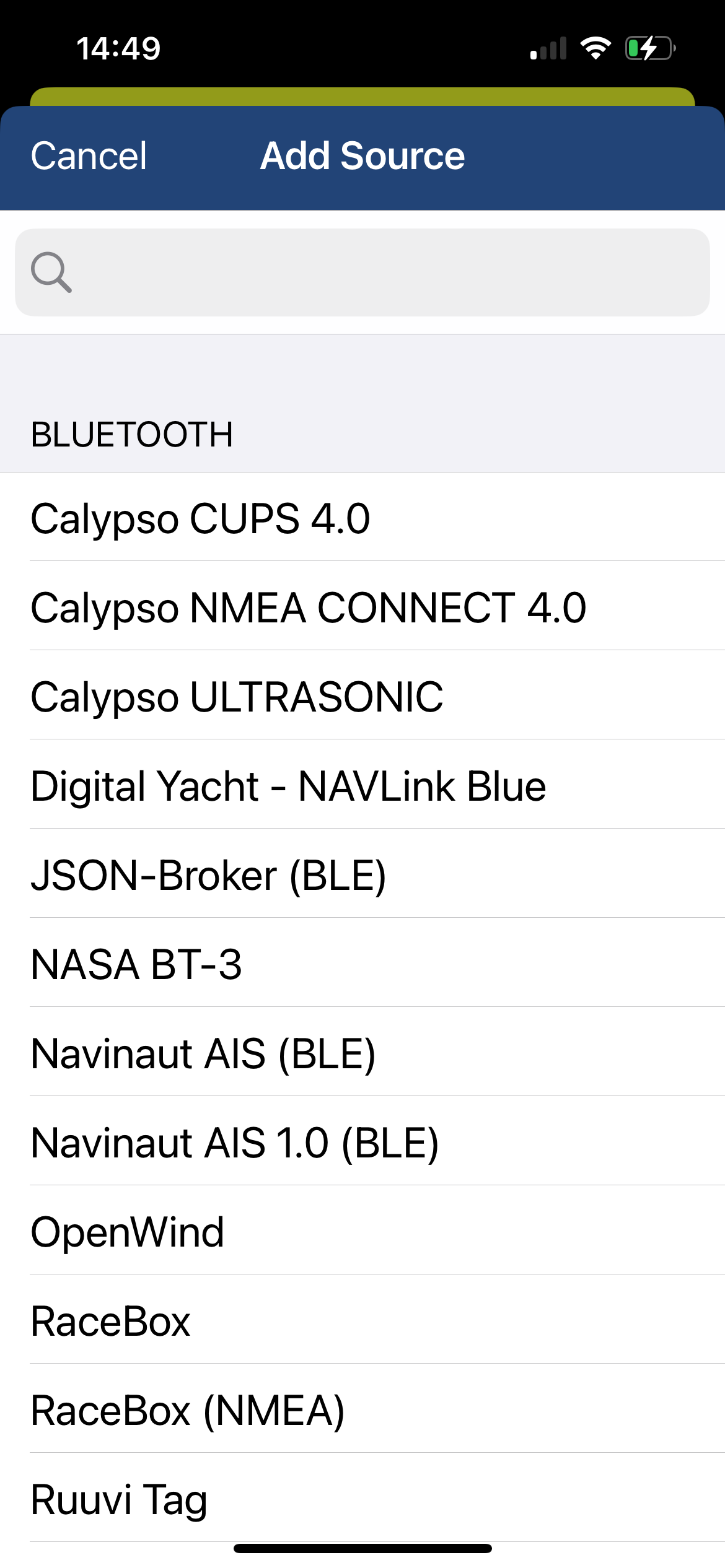
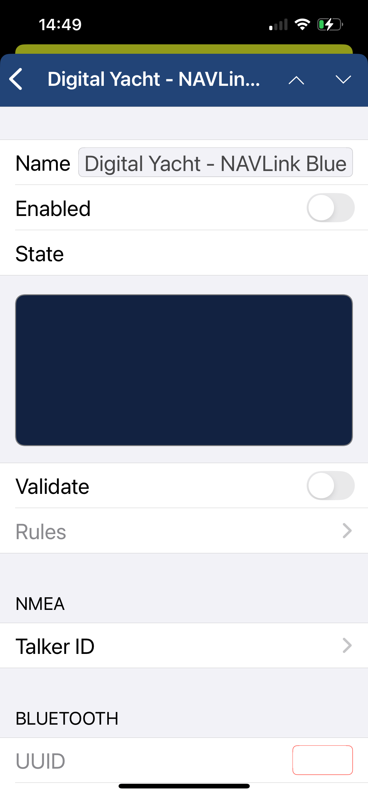
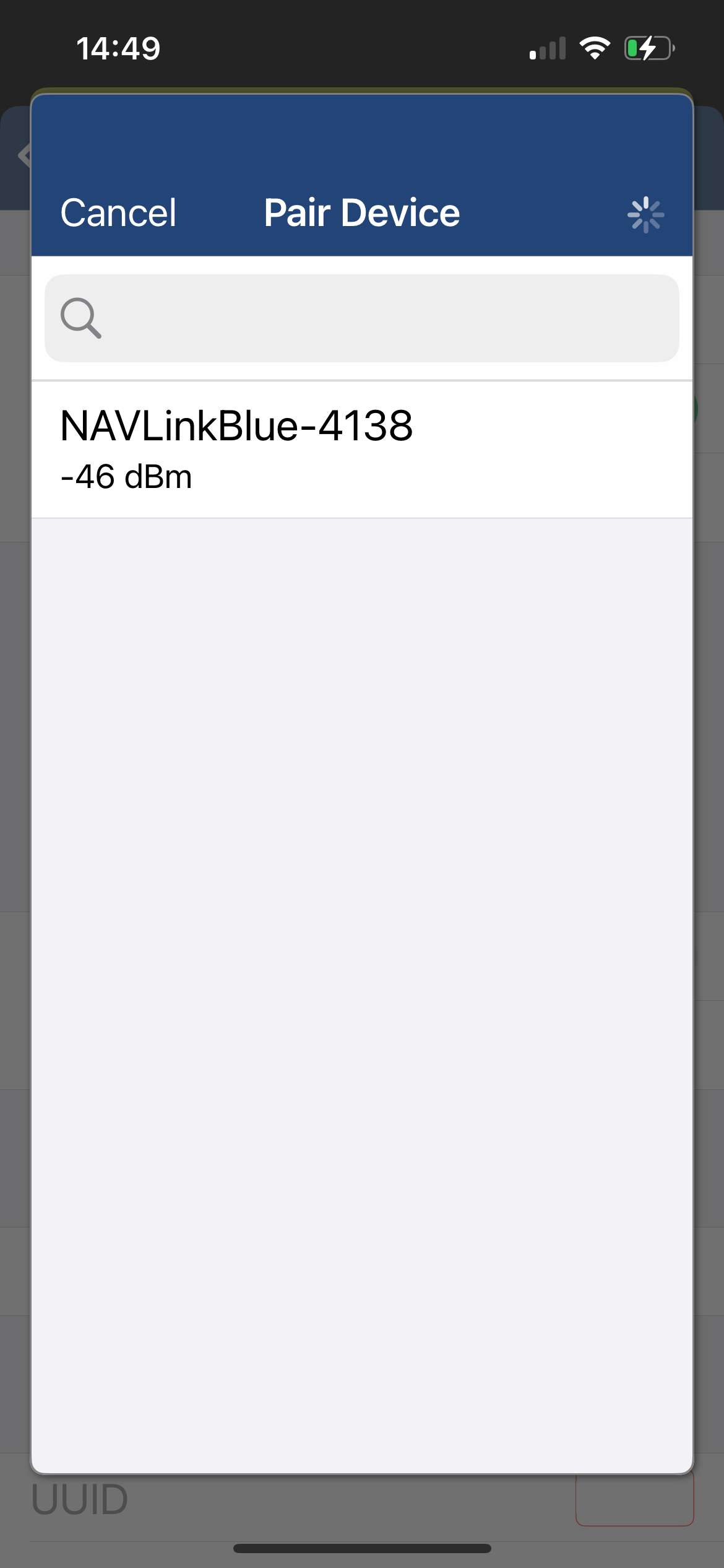
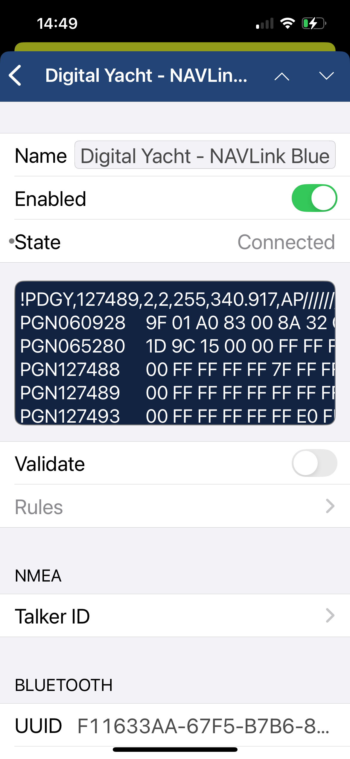
Ensure NAVLink Blue is in BT mode.
Then open NMEA Remote on your iPhone or iPad.
Tap Menu, then Settings (by clicking on “NMEA Remote” at the top of the menu).
Navigate to NMEA > Sources > Edit > Add Source.
The NavLink Blue uses Bluetooth Low Energy (BLE) instead of Wi-Fi. This offers:
- lower energy consumption
- a direct connection with Bluetooth sensors
- a new range of compatible devices.
net protect
NjordLink+
Yes – we can quickly and affordably develop a custom app. You can decide on how data is displayed and how to work with historical data for analysis. Contact us to get a quote.
Yes. Once provisioned, all data is uploaded to the cloud and can be viewed remotely via the NjordLink Plus mobile app, including map position and live NMEA 2000 data.
Yes – NjordLINK +has to deliver the boat data to the cloud so you need an internet connection. It doesn’t consume much bandwidth and we automatically reconnect if the connection drops. A simple phone hotspot, wifi, 4G/5G connection or satellite service such as Starlink can be used.
No. NjordLink+ uses its own 12–24V DC power supply.
Building apps with Njord cloud is easy using free APIs and scripts to quickly parse and query data. Contact us and get involved in our webinars online.
Yes. NjordLINK+ uses secure end to end encryption and you can decide who has access to your data online
If NJORDLINK+ temporarily loses its internet connection, no data is lost.
The unit automatically stores all NMEA 2000 data locally in its internal memory while the connection is unavailable. Once the internet connection is restored, NJORDLINK+ will automatically upload all stored data to the cloud, ensuring a complete and continuous data history.
NJORDLINK+ includes 30GB of internal storage, which is sufficient for extended periods without connectivity. However, if the vessel is expected to be without internet access for a long time, it is recommended to power down the unit to avoid filling the storage with unnecessary data.
This process is fully automatic and requires no user intervention.
NjordLINK+requires a NMEA 2000 connection and also needs to wirelessly link to the boat’s internet network so position close to the internet router in a protected area.
nmea 2000
The Digital Yacht iKonvert NMEA 2000 to NMEA 0183 Converter is an intelligent and flexible gateway. Therefore allowing for new NMEA2000 equipment to talk to legacy NMEA0183 equipment. Conversions are bi-directional.
For example, you may want to get the data from older NMEA0183 sensors on to your NMEA2000 network. Another reason being you have a new NMEA2000 only MFD and want GPS and Navigation data sent to your older NMEA0183 VHF and Autopilot.
iKonvert can be used to accurately and intelligently carry out the required data conversions.
You cannot just plug two NMEA 2000 devices together with a suitable NMEA 2000 cable – they must be connected to a properly constructed NMEA 2000 network.
Each device has an NMEA 2000 interface that must be powered from the network. Some smaller low power devices, like sensors are also powered from the network
There is a small cost in setting up the network, but future expansion is very easy. A Digital Yacht NMEA 2000 Starter Kit is a cost effective way to build a small, expandable network
NavAlert is Digital Yacht’s latest innovation and allows an alarm to be set for any parameter that’s available on the boat’s NMEA 2000 network. That could be navigation data such as depth, heading or speed, electrical data such as voltage and engine/generator data including temperature, pressure, tank levels, fuel flow etc.
It connects anywhere on the NMEA 2000 network and also takes power from this connection so installation is super simple. A local WiFi network is created by NavAlert so setup is possible via any smart phone, tablet or PC. Simply choose the parameter you want to monitor and set an alarm level. Multiple parameters can be monitored.
NMEA 2000 networks are very reliable and really are “Plug and Play”. When things go wrong, it is not always easy to fault-find even on a small NMEA 2000 network.
NAVDoctor is the perfect NMEA 2000 diagnostic tool for dealers, installers and boat builders. It turns any mobile device in to an NMEA 2000 network analyser, creating simple and clear web pages that show the health and status of your NMEA 2000 network.
A key consideration in any good NMEA 2000 network design, is the total current that the network is consuming. If the total current is more than the safe current capacity of the NMEA 2000 cabling (3A for all Digital Yacht cables) then the cable could melt or even cause an electrical fire.
- Each device on the NMEA 2000 network consumes some current
- It is very important that the total network current is known and that it is less than 3A
- Every NMEA 2000 certified device, has a Load Equivalency Number or “LEN” for short
- 1 LEN = 0.05A (50mA)
- The LEN number will be printed on the devices product label (see example below)
- Add up the LEN values of all devices and make sure the total is less than 60 LEN which equals 3A
Digital Yacht NMEA 2000 Starter kit includes:
- 4 way T-Piece Backbone
- 2x Terminators
- 1m Power Cable (fused)
- 1m Drop Cable
The part number is ZDIGN2KIT.
NMEA 2000 is the marine version of the CAN networks found in every modern car. NMEA 2000 allows marine electronic devices from different manufacturers to talk to each other
NMEA 2000 is a standard set of data messages, protocols and connectors that all NMEA 2000 devices must use*
* Note – Some manufacturers have created their own “flavours” of NMEA 2000 with different connectors and cabling; Raymarine’s “SeaTalkNG” and Simrad’s “SimNet” are two examples and both need proprietary adaptor cables to connect to standard NMEA 2000 networks.
The list below, gives you all of the key NMEA 2000 networking rules that, if followed, will ensure your NMEA 2000 network works correctly.
- The network must be properly terminated; only two terminators fitted one at each end of the backbone
- The NMEA 2000 Supply voltage must be between 9V and 16V
- The NMEA 2000 Supply current must be less than 3A (60 LEN)
- Maximum number of 50 physical devices on the network
- The NMEA 2000 backbone must be less than 100m
- Maximum single drop cable length is 6m
- Total length of all drop cables must be less than 76m
- The volt drop from one end of the network to the other, must be less than 1.5V
NMEA 2000 to BT
Yes. Using the SDK provided, developers can create their own Bluetooth integrations and connect new sensors or systems to the NMEA 2000 network.
No. The NAVLink Blue operates either in continuous data transmission mode to NMEAremote (or other applications) or in scan mode for nearby Bluetooth sensors such as RuuviTags. It is not possible to use both modes simultaneously.
No. It is designed as an NMEA 2000 ↔ Bluetooth gateway (and Wi-Fi for configuration), but is not intended to replace a WiFi router.
Yes. It is immediately operational in Bluetooth mode and can send NMEA 2000 data to the NMEAremote iOS application without advanced configuration.
No. Simply connect the NAVLink Blue to the NMEA 2000 backbone.
Yes. The NAVLink Blue complies with the NMEA 2000 standard and works with all N2K-certified equipment: wind sensors, speed or depth probes, GPS, environmental sensors, etc. It is also compatible with the Raymarine SeaTalkNG standard via an NMEA 2000 to SeaTalkNG connector adapter.
The range varies depending on the environment. In general, it is 10 to 15 metres. However, please note that steel or carbon fibre hulls can significantly attenuate the signal and require more careful installation.
nmea to wifi
No internet connection is required. Many consumers get confused and automatically associate wifi with internet. The product creates a wifi network and the local iPad or tablet users searches for this in the same way they search for a wifi hotspot.
Once connected, NMEA data is sent over the local link created on board the boat.
All you need is to connect the NavLink2 to your NMEA 2000 backbone. It will take its power automatically from your NMEA 2000 network.
On our blog, we maintain a list that explains how to configure all the most popular navigation apps and software. The guide covers both how to set up an NMEA connection (UDP/TCP) and how to configure the AIS settings within each app or software package.
To see the list, please click here: https://digitalyacht.support/tutorials/how-to-configure-apps-software/
All configuration can be done through a simple web interface, just connect to the product’s Wi-Fi network then open your web browser, enter the product’s IP address (192.168.1.1) and you can set network name, mode, view data, password and join an existing network.
We keep on our blog a list which explains how to interface the WLN10/WLN30 & NavLink2 to popular navigation equipment such as Raymarine, Garmin, Furuno, etc.. This list explains which wires you need to use to interface the products together.
For the WLN10/WLN30, you can see the list here: https://digitalyacht.support/tutorials/how-to-interface-wln10/
For the NavLink2, you can see the list here: https://digitalyacht.support/tutorials/how-to-interface-nmea-2000/
Yes! You can program this through the web interface so you just have one Wi-Fi network on board with our product linked directly to your other Wi-Fi network as a client.
This works well as well with Furuno WiFi radar installations.
Our WLN10/WLN30 & NavLink2 have a built-in web interface and create a password protected WiFi network. With your tablet, PC or smartphone, if you scan for wireless networks, you should see a wireless network called “DY-WiFi-xxxx” where xxxx is a four-digit code unique to the product. The WiFi network might change according to your product version.
Make your device join this network and you will be asked to enter a password which is “PASS-xxxx” where xxxx is the same four-digit code as in your network name. You can change both the network name and password in the unit’s web interface.
For example, if your product creates the WiFi network: NavLink2-D4B6 then your password is PASS-D4B6
The Wi-Fi will typically footprint a boat up to 25m LOA. Contact us if you need a bigger footprint or have a steel or carbon vessel.
The WLN10 has a single NMEA 0183 interface (input and output). This interface must be configured to operate at either 38,400 baud (AIS speed) or 4,800 baud (GPS and instrument data speed). It is an ideal solution if you want to broadcast data from either an AIS receiver/transponder or from your onboard instrumentation.
The WLN30 features three NMEA 0183 interfaces, each of which can be configured to operate at a different baud rate. The WLN30 multiplexes all incoming data and broadcasts it via Wi-Fi, enabling real-time data delivery to navigation software or applications. This makes it an ideal server for vessels with multiple navigation devices operating at different NMEA speeds, where AIS, GPS, and instrument data need to be broadcast simultaneously.
We keep up to date reviews on our news blog at www.digitalyacht.net – search for Best Marine Apps for Android or iOS. Popular apps include Boating Navionics, TZ iBoat, Savvy Navvy, Navimetrix, OpenCPN, iAIS, NavLink, iSailor, SeaPilot, Adrena, Weather 4D, MaxSea TimeZero, SailGrib and literally 100s more.
Any navigation app or software that is NMEA-compatible can receive data from our products.
Our products are also fully compatible with navigation software running on PC, Mac, and Linux platforms.
nomad
Yes you can. You may need a SO239 to BNC adaptor as Nomad uses a BNC antenna connector. However, for best performance use an AIS tuned antenna but a normal VHF antenna will function.
The GV30 antenna can be used as an emergency VHF antenna. Remember it has a BNC connector so a BNC to PL259 adaptor may be required for a regular VHF
No internet connection is required for AIS apps to run and non GPS/WiFi only tablets can be utilised with an appropriate app for navigation as Nomad provides a GPS feed.
Nomad 2 has a built in interface for programming – simply connect your mobile device to its wifi and login to its functionality. No apps are required. proAIS 2 programming software can also be used on a PC or MAC via the USB interface
Nomad 2 has a USB interface (for power and data) that can connect to a PC or MAC. Any AIS compatible navigation software can be used and the PC will create a virtual com port. Digital Yacht offer free SmarterTrack Lite viewing software as well as premium SmarterTrack software for use with Navionics charts for detailed charting and navigation. It’s also compatible with popular programs like TimeZero, Nobeltec, Expedition, SeaPro and Open CPN. Most modern programs also accept a TCP/IP or UDP feed via the wireless link, but do double check before purchasing.
Apps on iPads, tablets and smartphones will use the wireless link to connect to Nomad. Check www.digitalyacht.net for iOS and Android apps as there are a huge number of popular charting and navigation programs.
Up to 7 devices can connect wirelessly to Nomad at any time, which supports TCP (single device) and UDP (multiple devices) protocols.
If the AIS transponder doesn’t have a built-in VHF splitter (i.e. AIT5000), there are 2 options: either install a dedicated VHF antenna for AIS or install an antenna splitter so that the main VHF antenna is used for both VHF radio and AIS.
For those who want to use their existing VHF antenna, then we recommend the use of a certified zero loss VHF antenna splitter such as our SPL1500 and SPL2000. Please do not use a non-zero loss certified VHF antenna splitter. They are inexpensive, but they can destroy your AIS transponder.
For those who want to install a VHF antenna dedicated to AIS, then we recommend a VHF antenna tuned to AIS frequencies. The AIS transmission and reception works on 2 dedicated channels which use the frequencies 161.975 and 162.025 MHz (channel 87B and 88B). VHF frequencies in the maritime environment use frequencies from 156.0 to 162.025 MHz and most VHF antennas are designed to provide maximum gain on channel 16 (156.8 MHz). You can now find antennas on the market dedicated to AIS frequencies such as the HA156 antenna.
These antennas, dedicated to AIS frequencies, offer maximum gain at 162 MHz (which is the centre between the 2 AIS frequencies 161.975 and 162.025 MHz). So if you install a VHF antenna instead of a VHF antenna splitter for your AIS receiver or transponder, then choose an AIS frequency VHF antenna to compensate for the loss due to the installation of the antenna lower down than the main VHF antenna at the top of the mast. The graph below shows how a dedicated AIS frequency antenna (162 MHz) provides a better VSWR and therefore a better transmission and reception.
The Wi-Fi will typically footprint a boat up to 25m LOA.
Contact us if you need a bigger footprint or have a steel or carbon vessel.
onefix
Yes. OneFix has a password-protected WiFi interface that lets you wirelessly send GPS/GNSS data to charting apps on tablets, phones and PCs.
OneFix generate alerts on the NMEA 2000 network for issues such as spoofing or positioning errors, keeping you informed you of potential problems.
You can also fit a external switch input for MOB alerts. When paired with a compatible input panel, pressing the MOB button will generate an AIS MOB message on the NMEA 2000 network.
Yes. It includes built-in data logging and event-marking features.
Your logged position data and tracks can be used to review voyages, analyse performance, document routes, mark fishing spots, or share and export navigation history for planning and record-keeping.
The stored tracks can be exported in GPX and KML formats for use in mapping tools like Google Maps.
GNSS spoofing is when fake satellite signals trick a GPS into showing the wrong position.
OneFix protects you by using multi-constellation, dual-band GNSS technology to cross-check signals and detect inconsistencies. If suspicious data is detected, it can generate alerts on your network.
This helps detect and reduce false or manipulated signals, increasing navigation safety and reliability.
OneFix is a high-precision positioning sensor designed to deliver extremely accurate position fixes—typically better than 1 meter. Its primary purpose is to replace or enhance a standard GPS on board, providing sailors with more accurate and reliable navigation data.
Simply put, OneFix ensures you always know your boat’s exact position.
Traditional GPS receivers on your boat only use single-band GPS (usually L1). OneFix uses dual-band L1/L5 GNSS reception and multiple constellations (including GPS, Galileo, Beidou, and NavIC).
This gives improved accuracy and reliability, especially in difficult conditions.
The OneFix sensor supports NMEA 2000 for modern marine networks, NMEA 0183 for legacy systems, and WiFi for wireless connection to mobile devices and navigation apps.
OneFix will act as the main GNSS source of your navigation system.
S185
When paired with a Digital Yacht Aqua Compact PC, the S185 becomes a large, responsive chart and data display, letting you run advanced navigation software such as TimeZero with full touchscreen control.
The S185 has a 100mm VESA fixing point on the rear chassis, which is pre-drilled and tapped. This means it will fit any standard 100mm VESA mount.
However, in most installations, the S185 is flush-mounted into a panel using the supplied mounting kit. This is typically preferred for a clean, “glass bridge” style installation.
Yes. The front panel is IP65 rated for water resistance when correctly flush mounted, protecting it from splashes, spray, and rain on deck.
Yes. The capacitive multi‑touch screen lets you zoom, pan and control navigation software naturally with your fingers, even when wearing sailing gloves, so you don’t need a mouse or keyboard.
The S185 is a high‑brightness 18.5″ touchscreen marine display designed to be used with a PC running a navigation software.
It’s perfect for creating a powerful onboard navigation station, featuring a water-resistant touchscreen at an attractive cost compared to same‑size multi function displays.
You can also connect your multi function display to the S185 via an HDMI cable.
The monitor runs directly on 12V or 24V DC power and draws typically under 30W, making it efficient and easy to install on boats without heavy electrical requirements.
With 1000 nits of brightness and optical bonding, the S185 stays clearly visible in bright daylight conditions where typical screens struggle, making navigation easier when you’re out on deck.
seatalk1 converter
SPL1500/2000
Yes. The SPL1500 and SPL2000 operate on 12 V or 24V DC systems with low power consumption.
Having an active splitter with its own power source is important to ensure your VHF and AIS systems continue to work reliably and don’t fail.
Yes. The SPL1500 and SPl2000 are compatible with all Class B AIS transponders and receivers, as well as standard marine VHF radios.
You will only need to verify the connectors on your AIS and VHF.
There are several benefits from using a VHF splitter:
Saves space by avoiding the need for an additional VHF antenna for the AIS
Simplifies installation, you don’t need to run additional cables through the boat
Better AIS reception, as VHF works line of sight.
Our ZeroLoss™ technology ensures reliable AIS transmitting and receiving
The fail-safe design ensures that your main VHF radio remains connected directly to the antenna if the splitter loses power or experiences a fault. Your critical communication capability won’t be compromised.
The SPL1500 and SPL2000 allow you to share a single VHF antenna between your VHF radio and an AIS receiver or transponder, eliminating the need to install a second antenna. T
his simplifies installation and reduces antenna clutter on your vessel.
vekonvert/BM100
As standard the BM100 includes a 500A shunt. 1000A and 2000A variants are available to special order. Please contact us.
Yes. Each battery bank will require a veKonvert interface.
Yes
veKonvert connects to the SmartShunt via the veDirect interface. All calibration of the boat’s battery capacity etc is done via the Bluetooth interface integrated into the SmartShunt. Download the Victron app and follow the set up instructions included with the SmartShunt. There’s no calibration required on the veKonvert interface
veKonvert is compatible with the following Victron products…
- BMV -700
- BMV -702
- BMV -700H
- BMV-712 Smart
- BMV-710H Smart
- BMV-712 Smart Rev2
- SmartShunt 300A/50mV
- SmartShunt 500A/50mV
- SmartShunt 1000A/50mV
- SmartShunt 2000A/50mV
- All MPPT Charge Controllers
NOTE – veKonvert is not compatible with Victron Chargers and Inverters. It should also not be plugged in to the VE.Direct interfaces of any Victron “Consumers” such as Multiplus, Quattro, Cerbo, etc.
Most popular MFDs show real time battery voltage, charge/discharge current, state of charge and capacity remaining. The Victron app will also provide additional historical information which is useful for battery maintenance.
velink
Yes. veLink centralizes alarms from connected Victron devices and sends them through the NMEA 2000 network, allowing your chartplotter or MFD to notify you if a device reports an issue.
No. veLink uses Bluetooth to receive data from Victron devices, so there’s no additional wiring on the Victron side. It simply plugs into your NMEA 2000 backbone and transmits the information wirelessly.
veLink is plug-and-play.
Simply connect it to the NMEA 2000 backbone and use its web interface to scan for and pair Victron Bluetooth devices using the connection key from the Victron Connect mobile app.
The interface also allows device naming and configuration of what data is sent over the NMEA 2000 network.
You can connect up to eight Bluetooth-enabled Victron devices simultaneously
Yes. The veLink complies with the NMEA 2000 standard and works with all NMEA 2000 certified equipment. It is also compatible with the Raymarine SeaTalkNG standard via an NMEA 2000 to SeaTalkNG connector adapter (Raymarine part number: A06045).
veLink can broadcast vital Victron electrical data to your multifunction display, including: battery status (voltage, current), state of charge (SOC), solar input, DC power information and alarm notifications.
The range varies depending on the environment. In general, it is 10 to 15 metres. However, please note that steel or carbon fibre hulls can significantly attenuate the signal and require more careful installation.
- SmartShunt, SmartShunt IP65, BMV-712 Smart, compatible BMV-700/702 via VE.Direct Bluetooth Smart Dongle
- BlueSolar / SmartSolar MPPT, including VE.Direct and selected VE.Can SmartSolar models that use the Instant Readout solar format if they have Bluetooth adapter.
- Blue Smart IP65, IP22, IP67 and related Blue Smart AC chargers
- Phoenix Smart IP43 chargers family
- Orion-Tr Smart DC/DC chargers, isolated and non-isolated
- Orion XS DC/DC battery chargers
- SmartShunt and BMV configured as Smart DC Energy Meter
Please contact us if you would like to add a Victron device to the veLink compatible list.